






Setting impeller aerator clearance above a geomembrane liner
Setting the right clearance between an impeller aerator and a geomembrane liner protects pond infrastructure while supporting effective water circulation. Insufficient separation can expose the liner to contact damage, while poorly planned placement can compromise aeration performance and make maintenance difficult. The appropriate clearance depends on equipment design, operating water depth, anchoring arrangements, and liner installation conditions—not a universal distance.
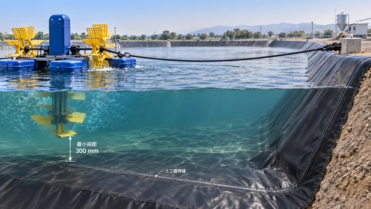
The practical question is not simply, “How far above the bottom should the impeller sit?” It is, “What is the smallest separation this installation will maintain during its permitted operating conditions?” That distinction matters when water levels fall, floating equipment tilts, or liner wrinkles project above the surveyed pond floor.
Define clearance from the actual equipment envelope
Measure clearance from the lowest component that could approach the liner, not automatically from the shaft centerline or nominal impeller position. Depending on the assembly, that component may be a blade tip, guard, intake housing, support frame, or hanging cable. Rotating parts require particular attention, but stationary components can also rub against the membrane when equipment moves.
Use the installed liner surface as the lower reference. A design drawing showing pond depth to the prepared subgrade does not establish clearance above the finished geomembrane. Wrinkles, repair patches, slope transitions, and local settlement can change the closest point.
For a floating unit, a useful preliminary relationship is: available vertical separation equals local water depth minus the lowest equipment projection below the waterline. Both values must represent the same location and operating condition. Then account for downward movement, tilt, liner projections, and measurement uncertainty without double-counting allowances. This is a geometric check, not a substitute for manufacturer approval or hydraulic assessment.
A section drawing should show the minimum operating waterline, equipment draft, movement allowance, highest local liner feature, and nearest slope. Vertical clearance alone will not protect a unit that can drift sideways into a lined embankment.
Obtain model-specific limits before fixing the layout
“Impeller aerator” covers different arrangements. A surface aerator and a submerged impeller assembly may have very different immersion requirements, discharge patterns, and movement characteristics. Motor power alone cannot establish a safe installation height.
Ask the equipment supplier to confirm these points for the exact model and configuration:
- Required immersion or draft, including any dependence on float loading.
- Minimum operating water depth and specified bottom or sidewall separation.
- Permitted tilt, mooring arrangement, and expected movement during operation.
- Discharge direction and restrictions for lined ponds or nearby obstructions.
- Low-water shutdown requirements and access needed for servicing.
If the manual gives no geomembrane-specific clearance, request a documented technical review. Silence is not confirmation that any visible gap is acceptable. The liner designer or installer should also review the proposal, particularly where concentrated flow passes over wrinkles, unsupported areas, or repaired sections.
Check the lowest water level, not the commissioning level
A floating aerator follows the water surface downward. An installation that looks generous when the pond is full may become unsuitable during drawdown, harvesting, water exchange, or an unplanned loss of water. Establish the lowest permitted operating level before approving the equipment position.
For fixed equipment, falling water levels may instead compromise required immersion or cooling conditions. Raising the assembly to create more bottom clearance can therefore introduce a different operating problem. Bottom separation and immersion requirements must be checked together.
Where the acceptable operating range is narrow, a low-water alarm or shutdown interlock may be appropriate, subject to the equipment instructions and electrical design. Define its setpoint from the approved installation geometry and operating limits. A water-level mark is useful for inspection, but it should not be mistaken for an automatic safeguard.
Also consider sediment accumulation. Deposits can obstruct equipment before it reaches the liner, and hard debris trapped between a moving component and the membrane can cause abrasion. Maintenance planning should address both clearance loss and debris removal.
Control movement and flow without creating new liner hazards
Mooring design is part of clearance control. Wind, startup torque, and changing water levels can alter position or attitude. Lines should restrain the unit throughout its intended water-level range without pulling it into an unsafe tilt. Chains, loose cables, and anchor hardware must not drag across the geomembrane.
Do not place improvised concrete blocks or sharp-edged supports directly on the liner. If bottom support is unavoidable, its bearing area, protective layers, stability, and installation method require a project-specific detail. A loose sacrificial sheet is not automatically a safe solution; it can move, trap debris, or introduce snagging edges.
Mechanical separation also does not resolve every hydraulic risk. Concentrated discharge may cause loose liner areas to flutter or repeatedly flex. Whether this is credible depends on flow direction, velocity, liner restraint, and underlying support. Redirecting or relocating the aerator may be more effective than merely increasing its height, provided the revised arrangement still meets circulation requirements.
Resolve liner defects before commissioning
Inspect the proposed operating area before filling where possible. Record protruding wrinkles, exposed hardware, suspect seams, patches, and unsupported zones. Keep equipment installation routes controlled: dragging an aerator into position can damage a liner before operation begins.
Where the approved repair procedure calls for extrusion welding, equipment such as the Double Heating Extrusion Welding Gun BGT-610 Series can support repair preparation. Its independent hot-air and extrusion heating controls allow separate adjustment of substrate preheating and extrudate temperature. The listed 230 V supply and 3.0–5.0 mm welding-rod range are practical compatibility checks for site planning, not proof that a particular repair will be acceptable.
Confirm the geomembrane resin, compatible welding rod, approved procedure, operator qualification, and inspection requirements. Equipment temperature ranges are capabilities, not recommended welding settings. A completed repair still needs acceptance under the project quality plan, and it does not justify reducing aerator clearance.
Make clearance a documented operating condition
Before startup, verify the as-installed position, water depth, mooring geometry, cable routing, and closest liner features. During controlled commissioning, observe drift, tilt, vibration, and circulation from a safe location. Keep personnel clear of moving equipment and isolate power before physical inspection or adjustment. Surface turbulence alone does not demonstrate adequate circulation throughout the pond.
The handover record should identify the approved position, minimum operating water level, shutdown conditions, inspection responsibilities, and changes requiring reassessment. Relocation, replacement floats, altered moorings, or major liner repairs can invalidate the original clearance check.
Jinan Dingshun Import & Export Co., Ltd. combines geosynthetics, aquaculture equipment, and engineering equipment supply with procurement, quality inspection, customs declaration, logistics, and after-sales service. For this application, that coordination is most useful when equipment drawings, liner requirements, electrical supply details, and repair provisions are checked together before shipment. Final clearance approval should remain with the responsible project engineers, supported by model-specific supplier information and verified site geometry.
