






A permanent magnet aerator can use an existing motor drive when that drive explicitly supports the motor’s permanent magnet control requirements and matches its electrical and operating limits. Matching the kilowatt rating alone is insufficient. An induction-motor-only variable frequency drive, a soft starter or a contactor-based starter does not establish compatibility with a conventional permanent magnet synchronous motor.
The first decision is whether the proposed aerator accepts an external drive at all. Some assemblies include a dedicated controller; others expose motor terminals for a compatible inverter. Obtain the motor data sheet, connection diagram and controller requirements before approving reuse. These documents determine whether the upgrade needs parameter changes, additional feedback hardware or a replacement drive.
Identify what the existing “motor drive” actually does
The equipment already in the cabinet may control speed, reduce starting current or simply switch power. These functions lead to different retrofit options.
“Vector control” on a drive brochure does not settle the question. Vector control for an induction motor and control for a permanent magnet synchronous motor use different motor models. Likewise, a brushless DC motor with electronic commutation should not be treated as interchangeable with every motor described as PMSM. The exact motor designation and supported control method matter.
Match current, voltage and speed together
Compare the motor’s rated current with the drive’s continuous output current under the actual installation conditions. Cabinet temperature, altitude and switching-frequency settings can reduce available current. Starting a loaded paddlewheel or accelerating a high-inertia assembly also requires adequate short-duration current capacity. A drive with the same nominal power rating can still be undersized.
Voltage needs two separate comparisons: the incoming supply against the drive’s input rating, and the drive’s available output against the motor’s voltage requirements across the intended speed range. A supply-voltage label does not prove that the inverter can deliver the required motor voltage at maximum speed. Increasing the speed setting can encounter voltage limits as the motor’s back electromotive force rises.
Permanent magnet motors also require the correct relationship between electrical frequency and shaft speed:
Electrical frequency in hertz = shaft speed in rpm × number of pole pairs ÷ 60.
A motor with more pole pairs requires a higher electrical frequency at the same shaft speed. Confirm that the drive supports the required output frequency and motor pole count. Record any gearbox ratio separately: the motor speed entered into the drive is different from paddlewheel speed when a gearbox is present.
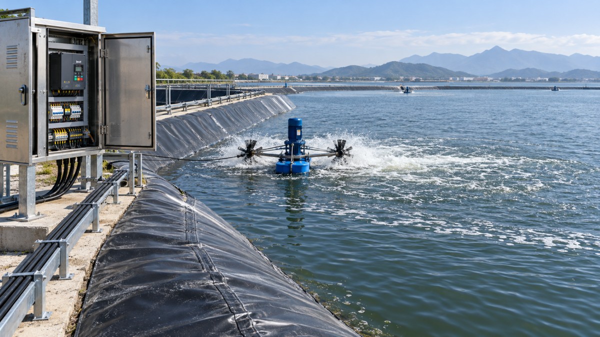
The permitted speed range must come from the complete aerator assembly. Motor capability alone does not establish acceptable impeller speed, gearbox loading, bearing limits or water engagement. Low-speed electrical operation also needs evaluation against cooling requirements and useful aeration performance.
Control compatibility can require information beyond the nameplate
A nameplate generally provides rated power, voltage, current and speed, but commissioning a permanent magnet motor can require winding resistance, inductance, magnet flux or a back-EMF constant. The drive manual identifies the required parameters and their units. Values expressed using different voltage conventions must be converted correctly before entry.
Sensorless control estimates rotor position without an encoder. Its suitability depends on the drive algorithm, motor characteristics and load during startup. Successful operation at normal speed does not demonstrate reliable starting from rest under the installed load.
If the motor requires an encoder, resolver or Hall signals, verify the drive’s feedback interface, signal format, supply voltage and connector arrangement. Adding a feedback card only resolves the issue when the drive supports both that interface and the motor’s control method.
Motor identification routines deserve particular attention. Some routines rotate the shaft; others identify parameters while stationary. A rotating routine can be unsuitable with an attached paddlewheel, restricted movement or an unexpected water load. Follow the approved identification procedure and establish whether the motor must be uncoupled. Saving the old induction-motor settings provides a rollback record, but those settings should not be transferred directly to the new motor.
Account for the pond installation and restart behavior
Long cable runs between a shore cabinet and an aerator affect inverter output conditions. Record cable length, conductor size, shielding, earthing and any existing output reactor or filter. Confirm the drive manufacturer’s cable limits and the motor’s inverter-duty insulation requirements. An output filter selected for the previous installation requires verification for the new drive mode and electrical frequency.
Water movement can leave a rotor turning when a start command arrives. Confirm that the drive’s flying-start function supports permanent magnet motors and the expected direction of rotation. A function documented for induction motors should not be assumed suitable. A turning permanent magnet motor also generates voltage, which matters during isolation and maintenance.
During deceleration, energy can return to the drive’s DC bus. Rapid stopping or a water-driven load can produce overvoltage trips if the stopping arrangement cannot handle that energy. Select coast stopping, controlled deceleration or braking hardware according to the aerator and drive instructions.
For a lined pond, cabinet supports, cable routes and anchoring must preserve the geomembrane. Where installation includes liner seams or approved modifications, equipment such as the HDPE Geomembrane Welding Machine BGT-GM Series belongs to the separate liner-work scope; its listed welding thickness range is 0.2–2.0 mm per sheet. Its electrical demand should be included in temporary site-power planning, independently of aerator drive compatibility.
Decide what to retain before ordering
Three practical outcomes follow from the compatibility review:
- Retain and reconfigure the drive when the exact model supports the motor, has adequate electrical capacity and can meet startup, speed and stopping requirements.
- A supported motor-control mode is available, but feedback hardware, firmware or an approved output accessory is required. Include these items and commissioning work in the retrofit scope.
- Replace the drive or use the aerator’s dedicated controller when motor support is absent, current or frequency limits are inadequate, or the required control interfaces cannot be accommodated.
Replacing the drive does not automatically require replacing the whole cabinet. Incoming protection, enclosure, supervisory controls and cables can be assessed individually. However, an existing bypass circuit that connected an induction motor directly to the supply must be reviewed before it is retained.
Make acceptance depend on operation under load
The approval package should identify the exact motor, drive model, firmware and required accessories, together with the parameter source and permitted operating range. A general statement that the equipment is “compatible with VFDs” leaves too much unresolved.
Commissioning should verify rotation, loaded starting, acceleration, stable operation at the required speeds, stopping and recovery after a supply interruption. Record current, speed, available temperature readings and fault history. Confirm that remote commands, thermal protection and emergency stopping behave as intended.
A brief unloaded run establishes only limited evidence. Acceptance requires stable operation with the installed water load and reliable restart behavior, using documented settings that can be restored after maintenance.