






Anchoring geomembrane ponds with fluctuating water levels requires more than burying the liner edge in a trench. The perimeter anchor must resist the loads transferred to it, while the liner, supporting soil, and drainage system must accommodate changing water pressure. A stronger anchor alone will not prevent uplift, slope instability, or damage caused by unsupported liner movement.
The critical design condition may occur when the pond is nearly empty rather than full. Drawdown removes water pressure that holds the liner against the subgrade, potentially exposing groundwater pressure, trapped gas, wind loading, and unstable saturated slopes. Reliable anchorage therefore starts with defining the operating water-level range and drawdown rate, then checking how those conditions affect the entire containment system.
Identify what will pull on the liner—and what anchorage cannot control
Water-level changes do not create a single, constant anchorage load. An exposed liner can experience wind suction and thermal movement; a submerged liner can experience wave action and movement of protective cover materials. Settlement, inadequate support at slope transitions, and sliding cover soil can also transfer tension toward the perimeter.
Groundwater introduces a different problem. If the hydraulic head beneath the liner exceeds the water level inside the pond, upward pressure can lift the membrane. A groundwater head difference of one metre produces approximately 9.8 kPa of pressure before accounting for resisting loads. Increasing trench depth does not eliminate that pressure; it can leave the perimeter restrained while the liner balloons between anchors.
Before selecting an anchor detail, establish:
- The maximum and minimum operating levels, emergency emptying conditions, and anticipated drawdown rates.
- Seasonal groundwater elevations, perched water potential, and possible gas generation beneath the liner.
- Slope geometry, crest stability, subgrade strength, and settlement susceptibility.
- Whether the liner remains exposed or supports soil, aggregate, concrete, or other protective materials.
- The temperature range during installation and service, especially across the exposed drawdown zone.
Rapid drawdown also requires a geotechnical stability check. Saturated embankment soil may retain pore pressure after the pond water falls, reducing slope stability. The geomembrane anchor is not a substitute for a stable embankment.
Choose the perimeter detail around the ground conditions
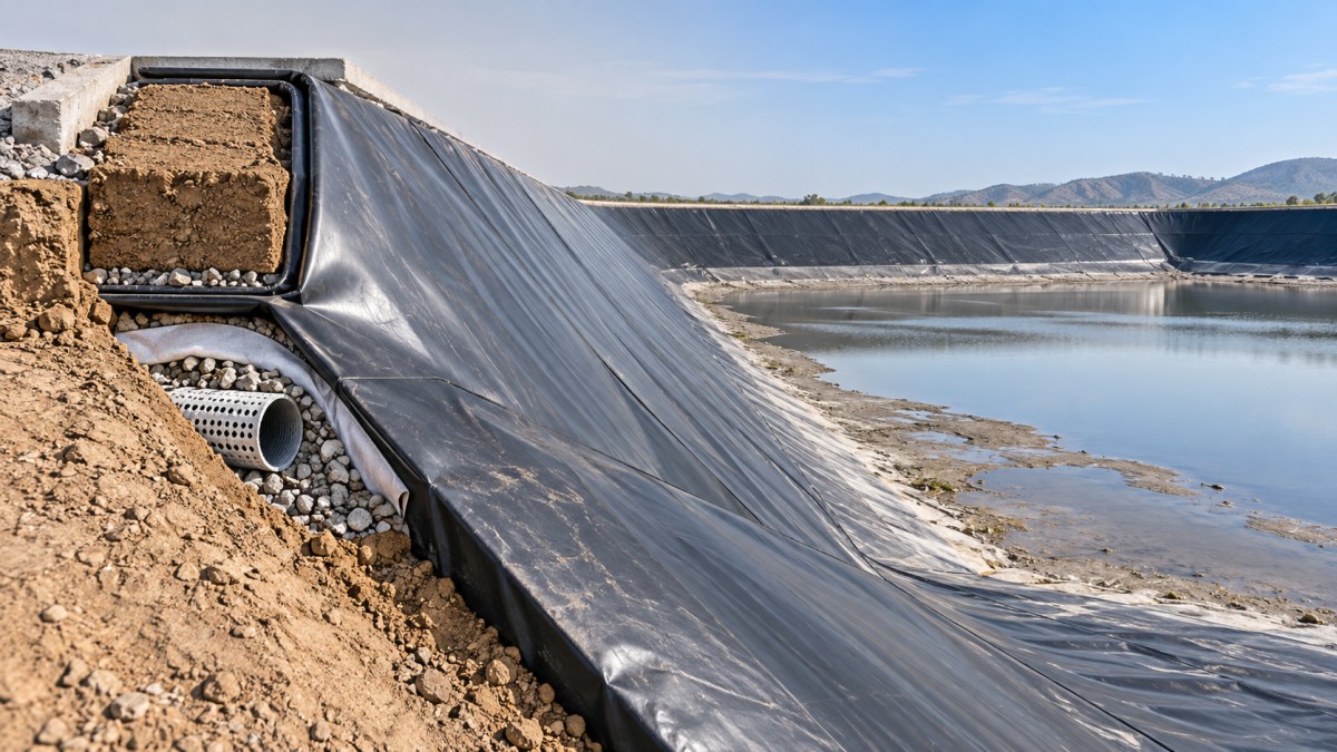
An anchor trench is a practical option where the pond crest provides sufficient width and competent soil. The liner passes over a prepared crest, turns into the trench, and is secured by designed backfill. Resistance depends on trench geometry, soil properties, compaction, liner interaction, and the direction of applied load—not simply the amount of material buried.
Trench depth, width, and setback should therefore come from project-specific calculations. A standard detail copied from another pond may be unsuitable where the crest is narrow, fill is weak, or groundwater affects the anchoring soil. Positioning a trench too close to the slope break can also compromise crest stability and leave inadequate soil to resist pullout.
The transition into the trench needs smooth, supported surfaces without sharp corners or bridging. Backfill should be compatible with the liner, free of damaging debris, and placed using a method that achieves the required compaction without puncturing or dragging the membrane. Surface grading should prevent runoff from eroding the crest or collecting around the anchor.
Where a liner terminates against a concrete wall, spillway, or other rigid structure, an engineered mechanical connection may be more appropriate. A typical arrangement uses a continuous batten or clamping bar, compatible gasket, and designed fasteners. The connection must address both load transfer and sealing; clamping a sheet tightly does not automatically create a durable watertight termination.
Fastener spacing, substrate capacity, corrosion resistance, gasket compatibility, and local membrane stresses require coordinated design. Bare bolts through an unsupported liner are not an acceptable substitute for a detailed connection. Transitions between trench anchorage and rigid terminations deserve particular attention because their different stiffnesses can concentrate strain.
Relieve underside pressure before adding restraint
If groundwater or gas can accumulate beneath the membrane, the design needs an appropriate pressure-management system. Depending on site conditions, this may involve underliner drainage, collection pipes, sumps, groundwater interception, or gas venting. The selected arrangement must maintain support beneath the liner while providing a reliable discharge path.
A drainage layer without a functioning outlet can store water rather than relieve pressure. Outlet elevations, downstream flooding, clogging potential, pump availability, and access for maintenance are therefore part of the anchorage decision. For contaminated-water ponds, collected liquids also need appropriate management; they should not automatically be treated as clean groundwater.
Ballast or protective cover can provide additional resistance, but it introduces its own loads. Cover materials must be checked for interface stability, puncture protection, and displacement during drawdown. They should not be assumed to remain stable on a slope merely because the liner beneath them is anchored.
Where pressure relief depends on pumping, the operating plan needs a response to pump failure. A minimum pond level or a restricted drawdown rate may be necessary under defined groundwater conditions. Such limits should follow the hydraulic and stability assessment, not a generic operating rule.
Allow movement without creating unsupported pockets
The liner should conform to the pond profile without being stretched tightly between the crest and floor. Temperature changes and settlement can otherwise produce tension at seams, penetrations, and anchor transitions. Conversely, excessive loose material can form folds that interfere with drainage, collect sediment, or become vulnerable to damage during filling.
Installation allowance should be specified for the selected polymer, panel layout, installation temperature, and geometry. Liner elongation at break is not an allowable working strain: it does not justify designing a liner to stretch under repeated operating loads.
Material identification matters here. Listings such as China geomembrane suppliers pond liner for wastewater treatment hpde pe geomembrane describe pond applications and offer LDPE/LLDPE material options across a range of thicknesses and widths. Those options require separate engineering review; a product title alone should not establish the polymer specified for construction. Confirm the resin type, thickness, dimensional behaviour, chemical compatibility, and applicable test documentation before approving the installation and anchorage details.
Where protective cover is used, interface shear testing with the actual material combination may be needed to evaluate sliding resistance. A textured surface or thicker sheet does not, by itself, demonstrate that the cover will remain stable through repeated filling and drawdown.
Make anchorage quality visible before it is buried
The construction sequence should include inspection hold points before critical details disappear beneath backfill. Confirm trench dimensions and setback, crest preparation, liner support, seam completion, and the condition of the membrane entering the trench. Record these details with surveyed locations and photographs suitable for the as-built file.
Temporary restraint is also necessary while panels remain exposed. Wind protection must use a controlled method that avoids sharp objects, concentrated loads, and uncontrolled displacement. Permanent backfilling should follow the approved sequence and temperature conditions; locking the perimeter while the liner is improperly positioned can preserve installation tension.
Seam quality assurance should include the specified nondestructive examination and destructive sampling, with repairs retested. Mechanical terminations need checks for substrate condition, gasket continuity, fastener installation, and specified tightening procedures. Where suitable for the liner configuration, electrical leak-location testing can provide an additional check before commissioning.
Initial filling should be controlled, with inspection of accessible anchor zones, exposed slopes, transitions, and penetrations. Unplanned bridging, growing folds, localized tension, or upward bulging warrants investigation rather than an assumption that additional water will resolve the defect.
Control drawdown as part of the anchorage system
The operating specification should state any minimum water level, drawdown restriction, drainage inspection requirement, and alarm response established by the design. Without those limits, even a correctly constructed anchor can be exposed to conditions it was never intended to withstand.
After significant drawdown, inspect the exposed liner and crest for erosion, displaced backfill, pullout, termination movement, and unsupported areas. Bulging suggests a need to investigate underside pressure; tension near a structure suggests a movement or support problem. Neither should be addressed automatically by adding more restraint.
The essential design test is whether the pond remains supported, drained, and stable across its operating range. Perimeter anchorage then provides a defined load path—not an attempt to make the liner carry loads that should be controlled by the ground, drainage system, or operating procedure.